Treon Industrial Node X installation location
Installation location
The aim is to pick an installation location on the asset that has the best measurable vibration and temperature reading for predictive maintenance of the asset.
As a general rule, mount the Treon Industrial Node X as close to the bearing load zone as feasible.
Avoid installation on thin covers or guards or loosely fastened parts that can resonate, such as for example motor fan cover. Also avoid areas where other machine parts or on-location personnel have a high chance of getting into contact with the sensor.
Avoid placing the Treon Industrial Node X to high temperatures locations over 85 °C and any other locations that might lead to sub-optimal sensor readings,damage to the sensor, or reduced battery life-time.
Always consult the product documentation of the asset before installing a sensor.
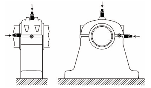
Horizontal machines
For machines with horizontal alignment or installation we propose the sensor locations depicted in the graphics below. In most cases, these will lead to optimal sensor readings on a horizontal machine.
Please note that the bearing load zone is typically located on the bottom half of the bearing.
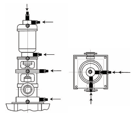
Vertical machines
For machines with vertical alignment or installation we propose the sensor locations depicted in the graphic below. In most cases, these will lead to optimal sensor readings on a vertical machine.
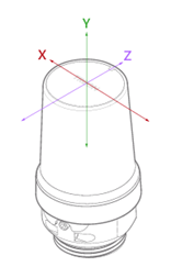
Node orientation and measurement directions
Align all Treon Industrial Node X sensors on the asset and across assets in the same direction whenever possible. Unified orientation helps analyzing the measurements as readings from sensor axis are directly comparable.
Align node axes as follows:
• Align one node axis to the assets horizontal direction
• Align one node axis to the assets vertical direction
• Align one node axis with the asset’s shaft direction
As a visual reference, use the Treon Industrial Node X’s safety‑screw opening which represents the node’s Z-axis.
Manual alignment of the node during installation requires a Treon Magnetic Glue Adapter for Flat Surface, Treon Magnetic Glue Adapter for Curved Surface or Treon Orientation Adapter. The Treon Bolt Mount Adapter does not allow axis rotation during installation or afterward.
It is recommended to always use at least one radial (vertical or horizontal) direction. Axial measurements should be taken at least in axial load carrying (thrust) bearing locations.
Mounting
Prefer bolt mounting and spot face drilling for best frequency response. For bolt mounting orientation adapter is recommended so that Node can be oriented properly.
Do not glue if there is a risk of damage to machinery in case the glue fails causing a sensor detachment.
Amount of Nodes
Preferably one Node per (key) bearing. If bearings are less than 25 cm (10 inch) apart, one sensor is sufficient to monitor both. This is valid for small motors, pumps, fans and gearboxes.
Good mounting practice
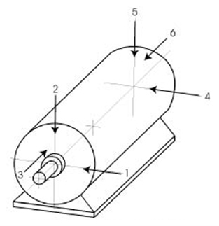
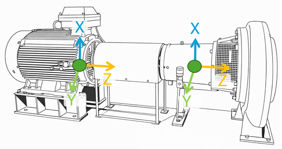
Example 1: Ideal sensor orientation on a horizontal machine.
The sensor node axes align with each other and to real world horizontal (Y), vertical (X) and axial (Z) directions. This helps when analyzing the data.
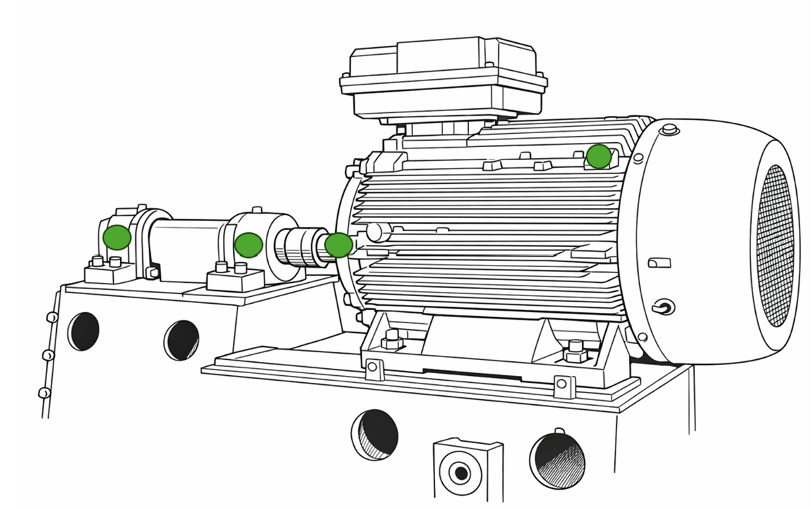
Example 2: Measurement locations on a large motor and overhung fan unit.
One sensor node is installed close to each of the bearings (two on motor and two on fan bearings housings). The node orientations are aligned, which makes sensor data analysis easier and enables comparization of sensor data across multiple sensors.
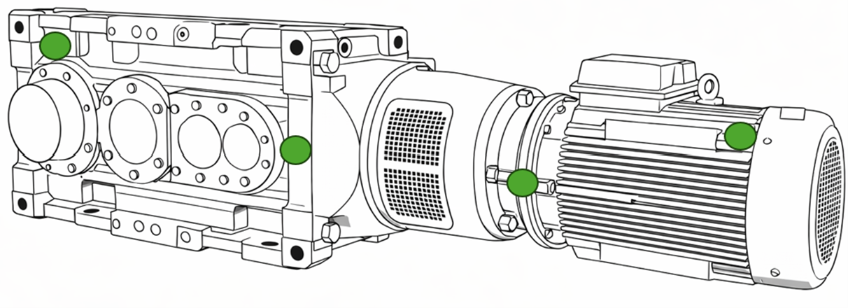
Example 3: Measurement locations on a large gearmotor.
Two sensor nodes are installed on the motor - one to the NDE (non-drive-end) and the other to the DE (drive-end). Two sensor are installed to gear - one near the input shaft and one near the output shaft.
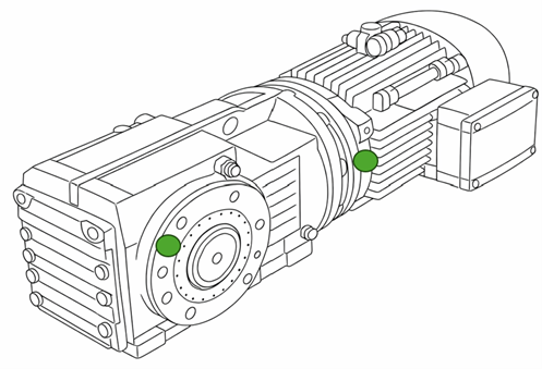
Example 4: Good measurement locations marked on a small gearmotor.
Two sensor nodes can be considered sufficient for this asset. One sensor is installed to the motor (DE (drive-end) usually offer better mounting surfaces than NDE (non-drive-end)) and one sensor is installed near the gear output shaft.
Improper mounting locations
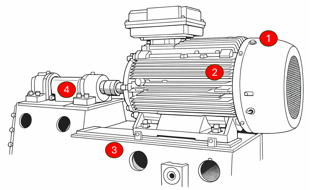
Mistake 1: Motor cooler fan cover mounting.
Installation of the sensor node on the motor cooler fan cover will predominantly pick up cooler fan vibrations which are not useful for asset condition monitoring.
Mistake 2: Motor cooler fin mounting.
Installation of the sensor node on the motor cooler fin will predominantly pick up cooler fin vibrations which are not useful for asset condition monitoring.
Mistake 3: Machine base mounting.
Installation directly on the machine base will likely be too far from the source of vibrations and only pick up dampened and mixed-up vibrations from the whole asset and not the parts to be monitored.
Mistake 4: Shaft cover mounting.
Installation on the shaft cover will likely be too far from the source of vibrations and only pick up dampened and mixed-up vibrations from the whole asset and not the parts to be monitored.
Troubleshooting
Error: Cannot identify the best mounting location.
Finding the ideal place to mount the Treon Industrial Node X to an asset might not be straight-forward and require some experience.Carefully read our instructions above on choosing a location. Think which vibrations you want to measure for ideal monitoring of your asset.
If you are still unsure about the mounting location, consider a specialist's consultation with Treon.
Error: Sensor data does not match previous data.
When another sensor previously installed on the asset delivered different vibration or temperature data, this can have a multitude of reasons.First, check that the Treon Industrial Node X is mounted in a location that picks up sensor data in a similar quality than your previous sensor in order to make it comparable.
Make sure the method the Treon Industrial Node X has been mounted with has been executed correctly and is suitable for the sensor location on the asset.
Check if both sensors have been aligned on the asset in a comparable way, and if sensor data from the same axes of the asset are compared.
Error: Sensor data does not match data from another sensor.
When another sensor currently installed on the asset delivers different vibration or temperature data, this can have a multitude of reasons.Take into account that two sensors cannot be mounted in exactly the same location, so that there will always be a difference in the data. First, check that the Treon Industrial Node X is mounted in a location that picks up sensor data in a similar quality than your other sensor in order to make it comparable.
Make sure the method the Treon Industrial Node X has been mounted with has been executed correctly and is suitable for the sensor location on the asset.
Check if both sensors have been aligned on the asset in a comparable way, and if sensor data from the same axes of the asset is compared.

Last updated on Apr 23, 2026